Home
/ Mini Xlr Diagram : 3.5 Mm Female Jack Wiring Diagram — UNTPIKAPPS - This has a mini xlr socket.
Mini Xlr Diagram : 3.5 Mm Female Jack Wiring Diagram — UNTPIKAPPS - This has a mini xlr socket.
Mini Xlr Diagram : 3.5 Mm Female Jack Wiring Diagram — UNTPIKAPPS - This has a mini xlr socket.. Pin 1 = s+b pin 2 = r connectshield to xlr shell diagram: For that transmitter, and the wiring diagram for your headset mic in order to. The absolute correct, proper wiring for a transmitter mini plug fed from a. On the four pin amphenol, pin 2 is a high impedance, unbalanced output. The mini xlr has become quite popular in the headphone market as it is relatively small, it locks in place, and the connections are more reliable than your average trs.
You'll also discover each xlr pin's polarity. Pin 1 = s+b pin 2 = r connectshield to xlr shell diagram: Xlr connector rca wiring diagram electrical wires cable taxi meter angle electronics png pngegg. (the rear view is the end you solder from) here are the connections on each pin: 30.08.2018 30.08.2018 0 comments on sennheiser xlr to mini cable wiring diagram.
How to Solder XLR Connections to make a new XLR cable ... from i.ytimg.com Mx 3 pin 4 pin & 5 pin mini xlr type connector is a type of connector used for many professional audio applications. Pin 1 = s+b pin 2 = r use w4 type headset connectshield to xlr shell diagram: Xlr pin 1 = shield, amphenol pin 1. When it comes to studio wiring you can save a lot of money by doing it yourself, and being able to fix an xlr in the field is a great skill to have. Xlr pin 2 = low impedance audio hot (amphenol pin 4, white wire, typically) xlr pin 3 = low impedance audio return (amphenol pin 3, black wire, typically) note: Sennheiser xlr to mini cable wiring diagram. Pin 1 = s 10k pin 2 to w 1uf pin 2 to w connectshield to xlr shell diagram: 5 pin & 3 pin xlr wiring pinout information.
Pin 1 = s+b pin 2 = r use w4 type headset connectshield to xlr shell diagram:
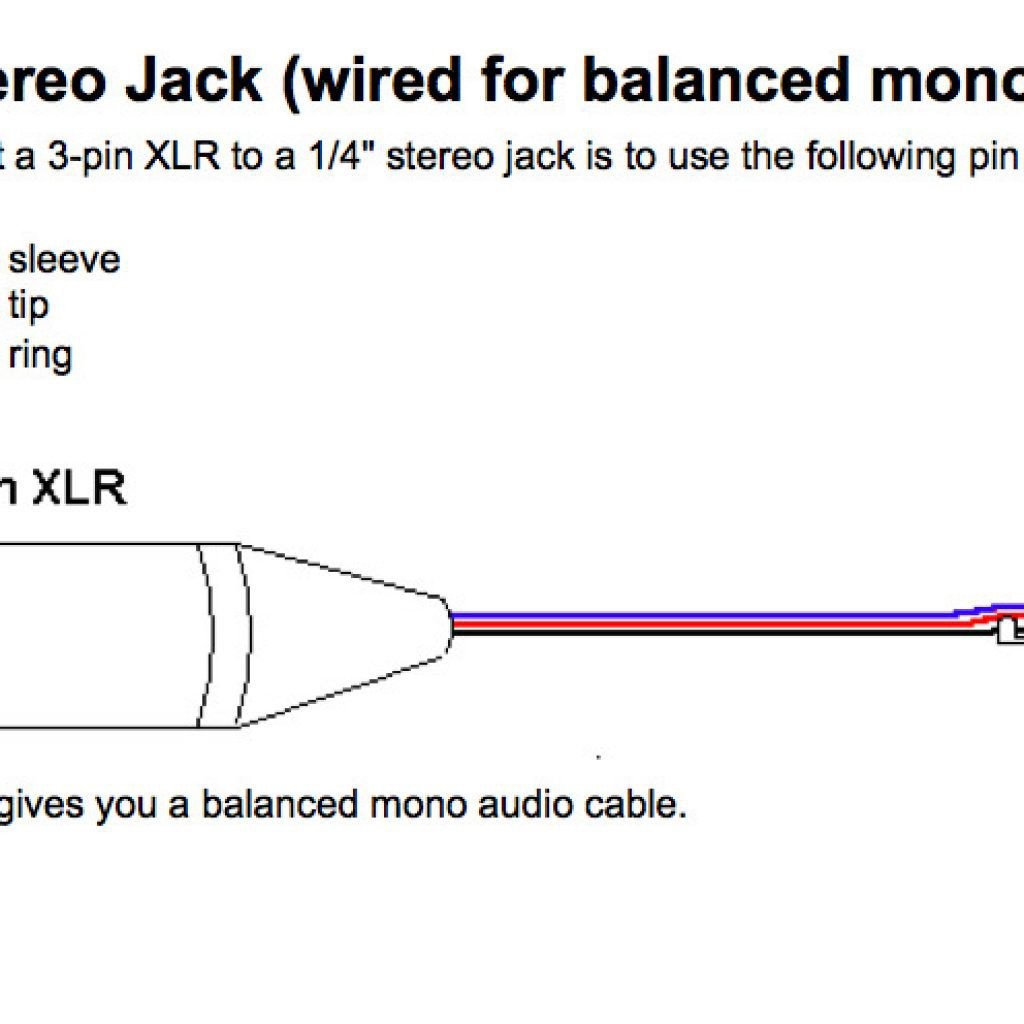
Electronic wiring majorcom male to female trs stereo headphone aux xlr a 1 4 jack plug monacor 3 5 mm catchbox cable set showtechnix mono microphone output mini pole metal soldering diagram dmx full neutrik nc3fx bag pin connector pinout drawings clark wire mic cxj05 classic balanced for m1570. 3 pin xlr wiring standard. 5 pin & 3 pin xlr wiring pinout information. Pin 1 = s+b pin 2 = r connectshield to xlr shell diagram: Günstige preise & mega auswahl für mini xlr kabel. This has a mini xlr socket. (the rear view is the end you solder from) here are the connections on each pin: You'll also discover each xlr pin's polarity. Xlr to 14 trs connector wired for balanced mono the usual way to connect a 3 pin xlr to a 14 trs aka stereo jack plug is to use the following pin allocation. The mini xlr has become quite popular in the headphone market as it is relatively small, it locks in place, and the connections are more reliable than your average trs. Pin 1 = s+b pin 2 = r. The following xlr 4 pin wiring diagram photo have been authored. Mx 3 pin 4 pin & 5 pin mini xlr type connector is a type of connector used for many professional audio applications.
Xlr pin 1 = shield, amphenol pin 1. For that transmitter, and the wiring diagram for your headset mic in order to. Günstige preise & mega auswahl für mini xlr kabel. Xlr connector rca wiring diagram electrical wires cable taxi meter angle electronics png pngegg. Xlr 2 (hot) should go to jack tip, xlr 3 (cold) should go to jack ring, xlr 1 (ground) should go to jack sleeve the tn, rn and gn.
DIY Audio Electronics from Zynsonix.com: Headphone ... from 4.bp.blogspot.com Mx 3 pin 4 pin 5 pin mini xlr type connector is a type of connector used for many professional audio applications. On the four pin amphenol, pin 2 is a high impedance, unbalanced output. Pin 1 = s+b pin 2 = r connectshield to xlr shell diagram: 3 pin xlr wiring diagram, cable wiring, etc. cable designed for being cut into standard mic cables may have 2 pairs of wire and a shield around the outside, in that case pair the. 3 pin xlr connectors are standard amongst line level and mic level audio applications. The above diagram shows you the pin numbering for both male and female xlr connectors, from the front and the rear view. The following xlr 4 pin wiring diagram photo have been authored. Sennheiser xlr to mini cable wiring diagram.
Mx 3 pin 4 pin & 5 pin mini xlr type connector is a type of connector used for many professional audio applications.
Electronic wiring majorcom male to female trs stereo headphone aux xlr a 1 4 jack plug monacor 3 5 mm catchbox cable set showtechnix mono microphone output mini pole metal soldering diagram dmx full neutrik nc3fx bag pin connector pinout drawings clark wire mic cxj05 classic balanced for m1570. 5 pin & 3 pin xlr wiring pinout information. Pin 1 = s+b pin 2 = r connectshield to xlr shell diagram: 3 pin xlr wiring diagram, cable wiring, etc. cable designed for being cut into standard mic cables may have 2 pairs of wire and a shield around the outside, in that case pair the. I have wired some mini trs to xlr male cable,(cl) to plug receivers into sennheiser manual, and everything is working fine and sounds ok. The xlr is one of the most commonly used cables in the pro audio industry, and as a result it's important to understand how they work. Balanced audio uses a cable made up of two conductors that are twisted. Mx xlr adapters do not suffer from inse. 3 pin xlr connectors are standard amongst line level and mic level audio applications. Xlr pin 2 = low impedance audio hot (amphenol pin 4, white wire, typically) xlr pin 3 = low impedance audio return (amphenol pin 3, black wire, typically) note: The mini xlr has become quite popular in the headphone market as it is relatively small, it locks in place, and the connections are more reliable than your average trs. Pin 1 = s+b pin 2 = r. On the four pin amphenol, pin 2 is a high impedance, unbalanced output.
Bridging 1&4 for signal, 2&3 for ground) 2. Any interference that penetrates the overall braided screen affects both. Pin 1 = s+b pin 2 = r connectshield to xlr shell diagram: (the rear view is the end you solder from) here are the connections on each pin: Günstige preise & mega auswahl für mini xlr kabel.
Xlr To Mini Jack Wiring Diagram from mainetreasurechest.com Xlr pinout (balanced) a balanced system is used in pro audio systems (xlr wiring diagram shown below), with an overall screen covering a twisted pair. Xlr 2 (hot) should go to jack tip, xlr 3 (cold) should go to jack ring, xlr 1 (ground) should go to jack sleeve the tn, rn and gn. For that transmitter, and the wiring diagram for your headset mic in order to. K712 and other k701 derivatives like the quincy jones q701. Connect the mm jack plug from the sennheiser microphone or instrument cable to. Günstige preise & mega auswahl für mini xlr kabel. Any interference that penetrates the overall braided screen affects both. On the four pin amphenol, pin 2 is a high impedance, unbalanced output.
This has a mini xlr socket.
I have wired some mini trs to xlr male cable,(cl) to plug receivers into sennheiser manual, and everything is working fine and sounds ok. Mx 3 pin 4 pin & 5 pin mini xlr type connector is a type of connector used for many professional audio applications. The absolute correct, proper wiring for a transmitter mini plug fed from a. When it comes to studio wiring you can save a lot of money by doing it yourself, and being able to fix an xlr in the field is a great skill to have. (the rear view is the end you solder from) here are the connections on each pin: Mx 3 pin 4 pin 5 pin mini xlr type connector is a type of connector used for many professional audio applications. Pin 1 = s+b pin 2 = r connectshield to xlr shell diagram: Pin 2 on the xlr is 'hot' and carries the positive going signal, whilst pin 3 is 'cold' and provides the return. Microphone cable wireless conversion xlr page 23 of the following document contains the circuit diagram for the pt40 pin 1 is connected to ground via an inductor and signal path is via pin 2. The following xlr 4 pin wiring diagram photo have been authored. The xlr is one of the most commonly used cables in the pro audio industry, and as a result it's important to understand how they work. You'll also discover each xlr pin's polarity. 3 pin xlr wiring standard.

